There are many ways of modeling bolted connections using ANSYS workbench FE software. This article provides an overview of various methods including best practices. Here is my list in order of increasing complexity and modeling fidelity:
- No bolts – bonded connections
- Beam Bolts
- Spring Bolts
- 3D solid bolts
- 3D solid bolts with joint pretension load
- 3D solid bolts with simulated threads
- 2D axisymmetric threaded connection.
This article covers methods 1-4. In part 2, methods 5-7 will be covered and in part 3, I’ll go into details of hand calculations and layout best practices for modeling bolted connections. As a test case, I’ll use the following model of a steel plate connected to a steel C channel (250 mm wide). The bolts are M16 (Mcmaster-Carr part #: 95327A761) and nuts are M16 (Mcmaster-Carr part #: 90685A120). A force of 1000 lbs is applied at the end of the steel plate and the C channel is fixed at the bottom as shown.
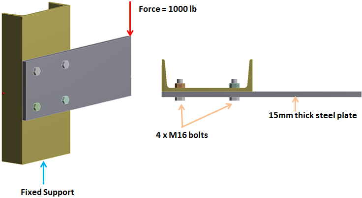
CAD model of bolted connection.
Here is a brief outline of various methods:
1) No bolts – Bonded connection:
This is the simplest connection. Bolts and nuts are removed from the assembly. A bonded connection is created around the bolt hole as shown. The bonded region can be taken as having a diameter equal to the washer used as shown in the figure. The bonded region simulates the friction grip of the joint around the bolted connection.
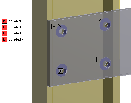
Bonded Connection
This type of connection is ideally used in the global analysis of large assemblies where modeling of bolts will become computationally intensive. A key assumption here is that the bolted joint maintains its friction grip and does not slip. A subsequent sub-modeling analysis of this bolted connection with 3D solid bolts will reveal its true integrity i.e., whether it slips or not. The bonded connection enables linear analysis which is much faster than a non-linear contact.
2) Beam Bolts:
The way to create Beam bolts is to import the CAD file into the design modeler and use bolt and nut head boundary edge to create imprints on the plate surfaces in contact with the bolt and nut (see image below). If a washer is used, then use the washer boundary edge for imprinting. Next, suppress the solid bolt and nut and open up the model in a mechanical application where beam connections are made via Body-Body -> Beam connection. For reference and mobile surfaces use the hexagonal or circular imprints created in the design modeler.
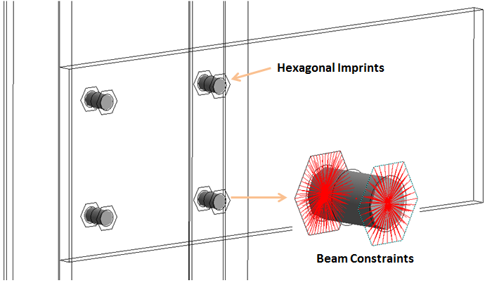
Beam Bolts. The red lines represent constraint equations that connect the beam element to bolted faces (hexagonal imprints)
The beam connection creates constraint equations between beam nodes and reference and mobile surfaces. The behavior can be set to rigid or deformable, although none of these options can capture the true stiffness of bolt head and nut. The bolt pretension can be computed using the following formula
Installed bolt pretension -> F = c At Sp
Where:
c = 0.75 for temporary connection and 0.89 for permanent connection
At = Tensile area of a bolt
Sp = Proof strength = 85% of yield strength of bolt material.
In recent versions of ANSYS bolt pretension can be applied on beam bolts. In earlier versions, APDL commands can be used. The contact between the mating plates is set to frictional.
3) Spring Bolts
The third type of bolted connection is a spring bolt. It is applied in a similar manner to beams. A pretension or pre-load value is defined in the details of the spring joint. In addition, spring stiffness “Ks’ is computed based on bolt shank geometry: Ks = E At/Ls. Where E is the young’s modulus, ‘At’ is the tensile bolt shank area and Ls is the shank length equal to the combined thickness of the mating plates.
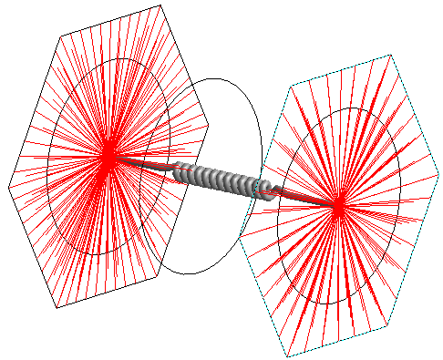
Spring Bolt
4) 3D Solid Bolts
This is the highest fidelity bolted connection model so far. This model enables us to capture the bolt and nut stiffness as well as post slip effect when the shank comes into contact with the bolt hole. The downside is significant computational cost, in particular, if there are several bolts in a big assembly. Therefore, this analysis is best suited to sub-modeling. The key steps in modeling solid bolts are shown below:
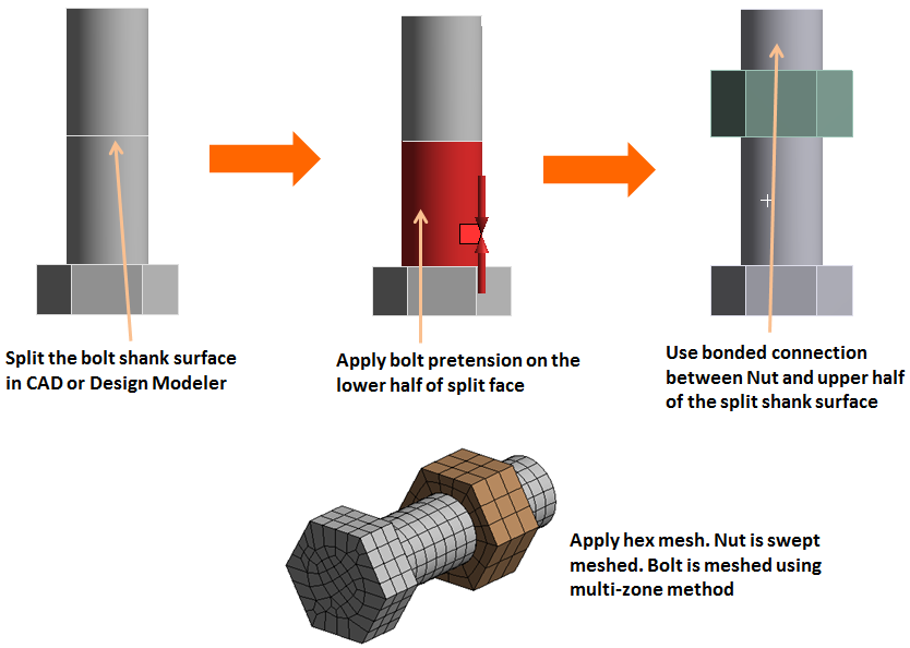
Outline of key steps in defining 3D solid bolt connection in ANSYS workbench
The bolt shank diameter should be based on ‘At’, the tensile area. This change should be made in CAD when converting the bolt for FEA analysis. It is also a good practice to remove any features such as chamfers, fillets, or protrusions in the bolt or nut body in CAD in order to obtain a nice mesh.
After the bolt is imported into the ANSYS Design modeler, the bolt shank surface should be split as shown via the projection method using the nut face edge. The splitting of the shank at the nut face is very important since the pretension load in mechanical will split the shank body in half and pull it together to impose the pretension load. The selected pretension surface should be separate from any bonded contacts such as nut-to-shank bonded contact, otherwise, it may cause problems when pretension is applied. The bolt should be hex meshed using the multi-zone method. There should be a frictional contact between the mating plate faces. The contacts between bolt head-to-plate and nut-to-plate can be either frictional or if bonded. Frictional contact is more realistic but is also computationally intensive. In the case of post slip failure of bolt needs to be analyzed, a frictional contact should be created between the bolt shank and plate holes. See the details of the contacts below.
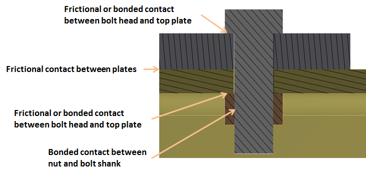
Solid bolt contacts
Simulation Results
The simulation results are shown below for:
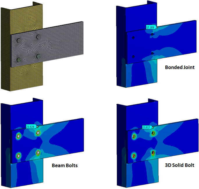
Comparison of simulation results
The simulation results for the beam and 3D solid bolts are almost identical in terms of stress contours as well as magnitude. The bonded connection results are clearly different. For all simulations, the identical mesh was used as shown above.
Post Processing Bolted Connection Results
Post-processing involves getting key results out of our analysis that we can use for making critical decisions. As far as the bolted connection is concerned, we can look at peak stress, contact slippage as well as the total axial load on the shank. The last one is used for the analysis of threads. For the beam bolts, finding axial load is straight forward using a beam probe. This gives us axial load, moment, and shear forces at nodes I & J. For the 3D solid bolt, we need to create a construction surface cutting the shank. This surface should not be located at least one or two elements away from the pretension split region otherwise we will get erroneous results. The split region is easy to identify by looking at total deformation as shown below.
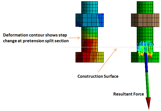
Post-processing for resultant force in solid bolts
Now in order to find the total force, we select force reaction probe > Location Method = Surface > then select the construction surface created above. This will give us the resultant force as shown above. Here is a brief comparison of bolted connection models. The contact behavior can also be displayed using the “contact tool”. Notice the sticking region has shrunk slightly after the application of full load. This shrinking implies local slippage of plates. If the sticking region vanishes, we consider that a failure of the friction-grip type bolted connection. The figure below shows the contact status of the solid bolt. The contact results for beam bolts are very similar if not identical.
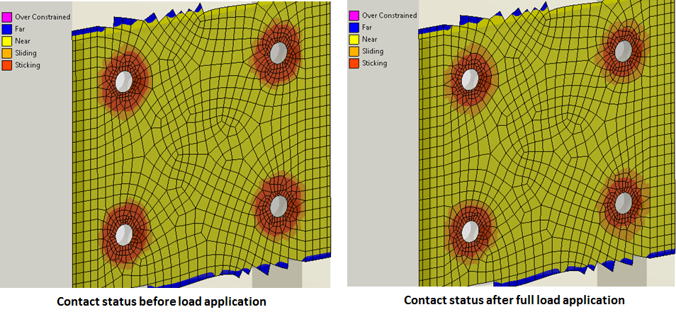
Contact status of 3D solid bolt model.
Conclusion
A summary table of key results is shown. Note that the spring-based bolted connection is identical to the beam bolt so its results are presented in this table.

Comparison of bolted connection models
These results show that the bonded contact model solves in a fraction of time compared to beam and 3D solid bolts. The difference is largely due to linear analysis in the case of bonded connection. The simulation time looks comparable for beam and solid bolts. However, in a sub-model comprising of many bolts, this difference will become significant. Beam bolts can also be used in global analysis, in particular, if the problem size is not very large. The downside is that a non-linear analysis will have to be performed due to frictional contact between the plates. Solid bolts should always be used in sub-models of critical joints in a big assembly.
If you have any question regarding this topic, please feel free to contact me at zaeem@endeavos.com


11 Comments
Really helpful guide, I now understand the basics of bolted connections and can’t wait to try it out in ANSYS Workbench!
Good day!
I have a suggestion regarding modeling the bolt pretension that may simplify your workflow.
Rather than splitting the bolt shank in CAD, you could define the entire bolt body as the pretension scope in Mechanical. Then, establish a local coordinate system with its xy-plane aligned parallel to and midway between the bottom face of the bolt head/washer and the top face at the start of the inner thread. This xy-plane would serve as the virtual “split plane” to simulate pretension.
As I see it, using a local coordinate system in this manner avoids the tedium of splitting the model geometry separately in CAD.
Any thoughts on that?
I look forward to following along with the progress of your project in Part 3.
Wishing you the best as you continue your work.
Great suggestion! and thanks for reading the article. Since I wrote that, a lot has changed in terms of software capabilities and modeling techniques. Seems like, its time I do an updated version of this article.
Regards,
Zaeem
very helpful,Thank you very much!
great article ?
Thanks a lot.
If you have some other example I will be glad to take them.
I’ll be writing part 3 soon…will post more examples. Thanks for your response.
good and usefull information thank you
Thanks and waiting for your next article…
good info